MIT Motorsports
High-speed Dynamometer
40kW, 20,000RPM motor test rig.
Background
MIT Motorsports is the Formula SAE Electric team here at MIT. Since 2025, our car has run a 4-wheel drive architecture with motors and gearboxes integrated into the wheel packages. This means that we have 4 brushless motors, each capable of about 30kW peak output, that are powered by a tabless battery pack based on 21700 cells.
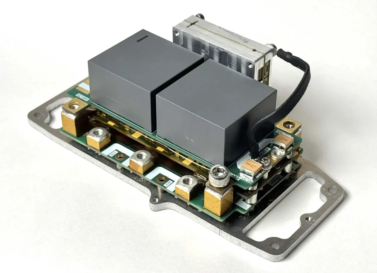
Four separate water-cooled inverters are required to control the four motors, and historically, we have used the inverters sold by AMK, the same company that manufactures the motors we use. These inverters are non-ideal for many reasons, mostly because it's design is from around 2014. Some of its issues include:
- Poor efficiency and low switching frequency due to dated IGBTs
- Poor over voltage protection, combined with a fault mode where all gates open, which causes a transient that can permanently damage it
- Extremely poor volume and mass efficiency — the 4 inverters take up more space than the battery
- Poor isolation, making it relatively unsafe, and many grounding-related noise / EMI issues
Despite all of these issues, almost all FSAE teams that use AMK motors also use these inverters. This comes down to the fact that it's extremely difficult to build a 600V inverter that can operate at the level of reliability needed for competition. In 2025, a subteam headed by Liong Ma began work on a custom inverter that could improve on the AMK hardware. Development took 2 years.
By Fall 2025, the hardware was nearing completion, and firmware development was beginning to speed up. One thing had become very clear.
Stable Controls Are Hard
In general, PMSMs follow the dq-axis model, where the voltage and torque equations are given by:
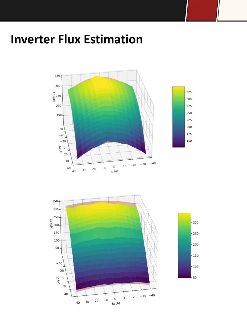
In the ideal model, Ld and Lq are treated as fixed constants. However, in reality, as current magnitude increases, the iron core of the motor begins to saturate, and the magnetic flux density stops rising proportionally with the applied field. Thus the incremental permeability of the core drops, and both Ld and Lq become nonlinear functions of the operating point (id, iq).
We ultimately observed that Lq peaks near zero id and rolls off symmetrically with iq, exhibiting cross-saturation, where flux in one axis suppresses permeability in the other. This cross-coupling term is often ignored in textbook controllers but becomes significant at high current levels. In our case, a more accurate formulation was required, which would replace the constant inductances with lookup tables Ld(id, iq) and Lq(id, iq), and add a cross-saturation correction:
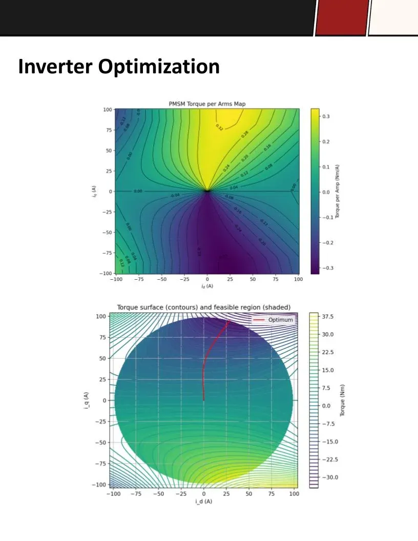
where Ldq is the cross-saturation inductance, and λd, λq are the full (nonlinear) flux linkage maps. The implementation of these lookup tables as part of a predictive deadbeat controller finally allowed us to achieve stable controls throughout the entire torque and speed range of the motors. But to get there, we needed hardware which would allow us to record clean output speed and torque data on the AMK motor output throughout its operating range.
The flight-critical nature of the inverters also meant that putting them on the car would require extensive bench testing, both to find its failure points and to size our cooling infrastructure on the rest of the car.
Enter the Dyno
This hardware took the form of a benchtop dynamometer, which had some unique design requirements:
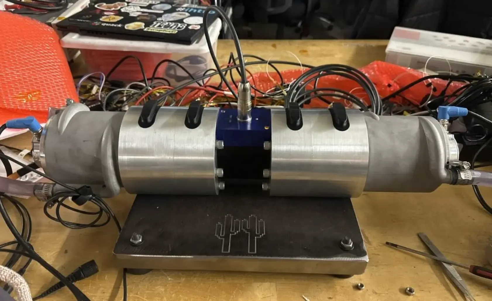
- Push a single (test) AMK motor to its operating limits. This necessitates a load, which is sometimes a disk brake, or passive magnetic brake. In our case, a second AMK motor is used, which can either act as a torque load proportional to velocity (via shorting the phases) or can be separately controlled by a second inverter for more complex tests.
- Accurately measure the output torque and speed throughout the operating range. For this we use a high-speed torque transducer supplied by HBK. It's rated to 20,000RPM and 21Nm of torque, just barely under the maximum achievable by the AMKs.
- Avoid vibrations. Since the torque transducer is essentially a load cell, vibrations would directly translate to noise in our measurements. This meant that the concentricity and axial colinearity of the two motors and transducer was a big concern.
- If the vibrations hit a resonant mode of the structure, the entire dyno could also tear itself apart. From the 20,000RPM top speed the operating vibration load case was set at 350Hz. With a 2.0FoS, we targeted a 700Hz fundamental frequency for the structure.
- Run for extended periods. This was perhaps the easiest design requirement to hit. Two aluminum 3D-printed cooling sleeves were used from the 2025 car. A miniature cooling loop with a pump and ice water keeps the motors and inverters cool.
MIT Motorsports has a robust design review process and this was my first introduction to it. For this project, I did a Design Requirement Design Review, Conceptual Design Review, and a Critical / Fabrication Design review, before I started machining.
DRDR
CoDR
CDR
Final Design
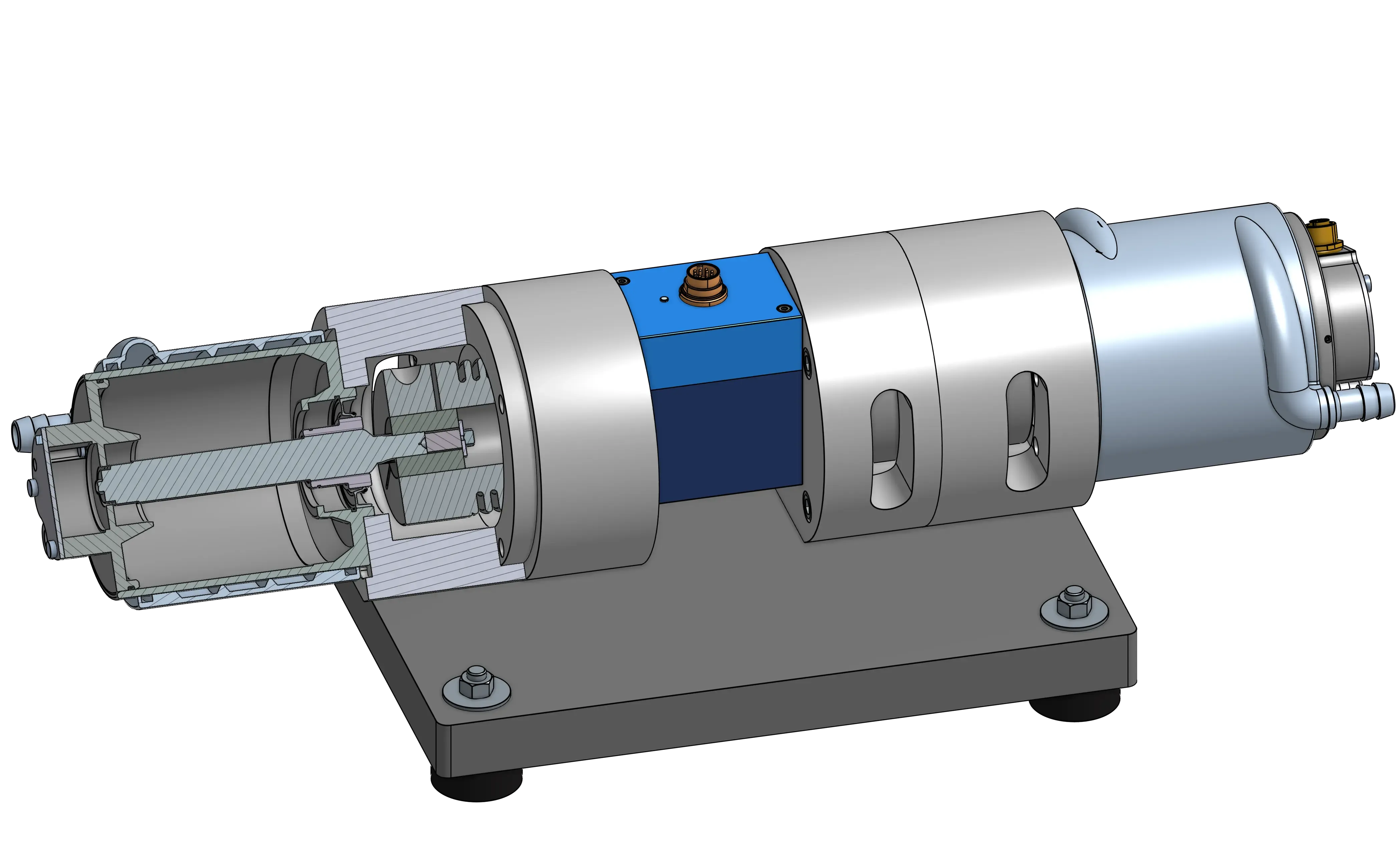
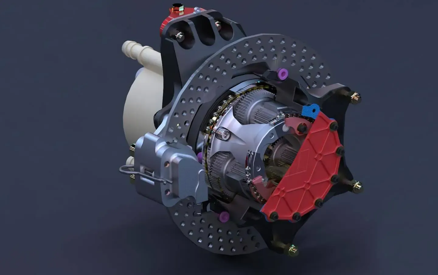
I'll be brief here since the DRs include tons of detail, but the final design uses two turned "uprights" on a steel base plate with rubber feet. The outputs of the motors are connected to (very expensive) flex couplers from HBK through wire-edm cut adapters that are then connected to each side of the transducer. The uprights were machined in two halves because the locating bosses on the AMK and transducer were actually smaller than the outer diameter of the coupler.
By turning each upright half on a single setup on our Prototrak lathe, the concentricity of each bore across the entire setup is precise. Each upright is located to the base plate with two dowel pins (one of which is fitted into a slot to avoid over-constraining the system). Two large cutouts were added so that the clamping collar could be tightened once the whole thing was assembled.
One of the most unfamiliar aspects of the design process with the dyno was my modal analysis, which was done in NX Simcenter. After modelling standins for the AMK motors with a similar mass and MOI, each part was meshed and then bolts were simulated with CBUSH and RBE3 joints with stiffnesses I calculated per axis. The Real Eigenvalues solver then gave me my modes:
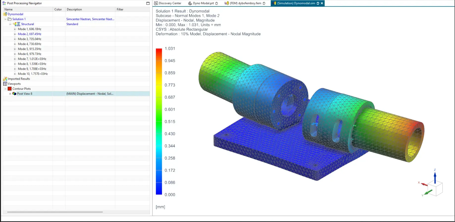
While I initially thought that the 700Hz design requirement would be easy to hit, the first solver run gave a fundamental frequency around 400Hz. This was concerning, but it turned out that I was losing the majority of my stiffness in the fasteners, which became clear when looking at the modes. I increased the bolts holding each upright half together from 4 to 6, and more than doubled the bolts holding the uprights to the base plate. I also increased the size of the dowel pins. After these changes I was able to hit a fundamental frequency of about 696Hz, which was good enough.
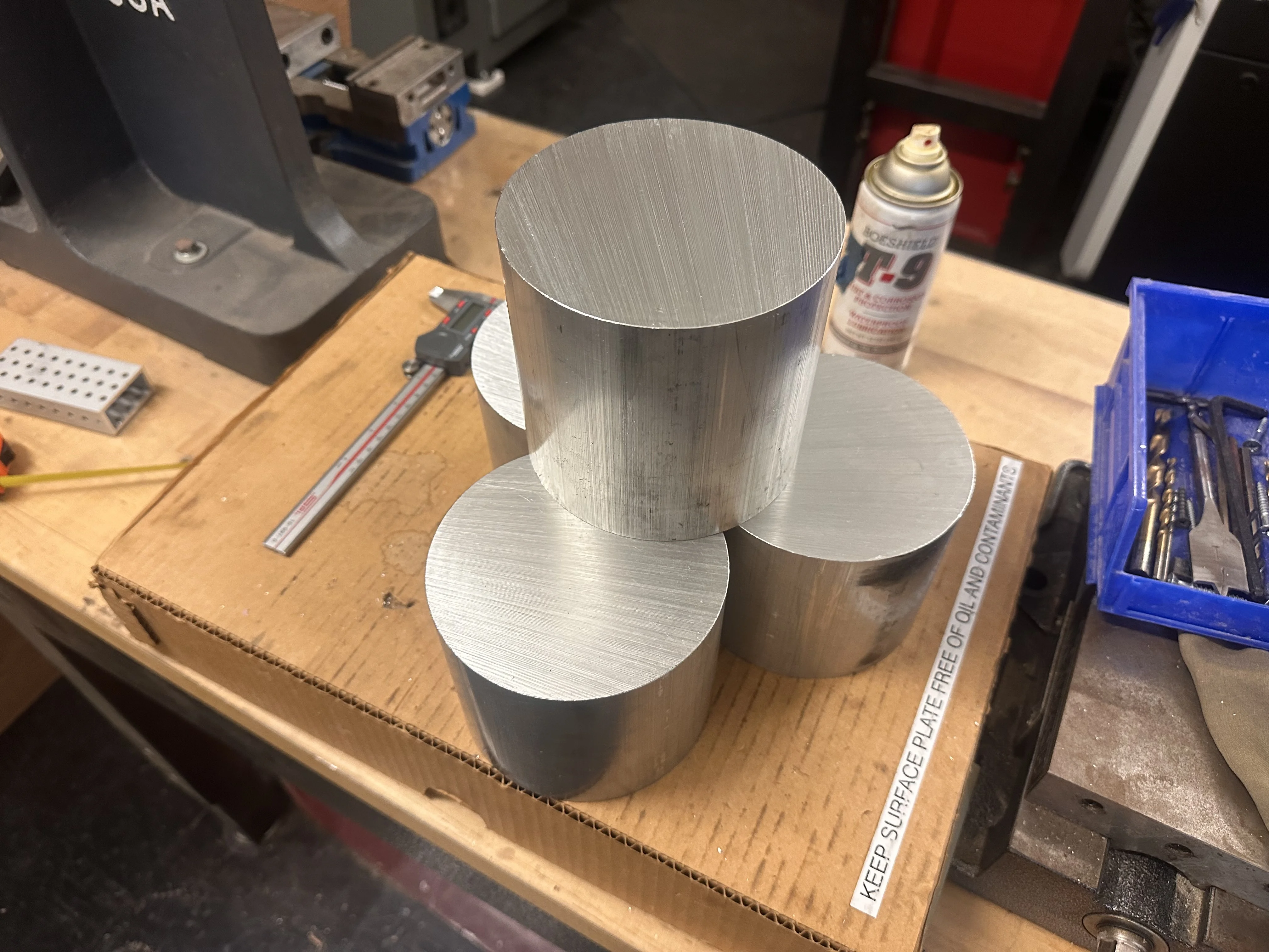
Even so, I assembled the dyno with Nordlock washers on all fasteners and red Loctite on critical retaining fasteners. Machining started with drilling the steel base plate on our VF2, followed by hours of lathe work boring out 5 inch OD 6061 stock and finishing on the fitted bores, and finally back on the VF2 to do the final operations on the aluminum parts.
Machining and Assembly
Results
The Dyno has been running since December 2025 and has allowed controls tuning and vetting of our custom inverter hardware for the 2026 car. Liong and his team got far enough with the custom inverter hardware that we moved to package all 4 inside of a housing with cooling hardware, in order to package it on the car, which became my next project. See that writeup here. Also, check out some of the data collected using the Dyno below. Credit goes to Liong Ma for setting up these tests and plotting the data.